18.Wireless technologies for WT
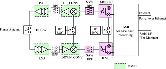
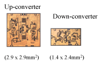
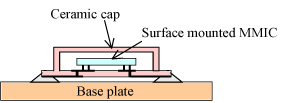
We developed analog devices to reduce drastically reduce the number of the components and to downsize the equipment. For example, up-converter and down-converter (Fig. 18), which require more than three circuits (mixer, multiplier, buffer amplifier, and so on) in each, are integrated into one-chip MMIC. This MMIC and PA are flip-chip mounted into a surface-mounted MMIC package (Fig. 19) that is also newly developed for the WIPAS.
The IF filters must have flat and low-ripple characteristics inside the pass band and steep attenuation outside the band, in order to obtain a large enough IRF, which is an important factor in designing high-density cells. We newly developed a Surface Acoustic Wave (SAW) filter that has those these characteristics as an IF filter.
Furthermore, an analog silicon IC was developed for the orthogonal modulator/demodulator to integrate the circuit. This silicon IC consists of a pair of a modulator and a demodulator pair with a composition of IF gain controllers.
 Figure 17 Configuration of WT |
|
 Figure 18 Up and Down converters |
 Figure 19 Surface mounted MMIC package |
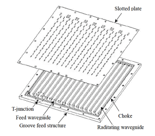
The WT planar antenna (18 cm x 18 cm; 31.5 dBi) is constructed with an alternating-phase fed single-layer waveguide array to obtain high gain, the ability for mass-production, and a low-cost structure. Fig. 20 illustrates the WT planar antenna. This antenna consists of a slot plate and a corrugated base, and is a part of the WT housing for inner components such as MMICs, an IF module and an Application Specific IC (ASIC). This planar antenna is also a part of the WT cooling element. A slot plate and a corrugated base are simply tacked together with surrounding chokes and do not require mutual electrical contact. This characteristic contributes to reducing the cost and size of the WTs.

|
17.Point-to-point (P-P)communication function |
TOP |
19.ASIC for base-band processing |
